DESIGNS>
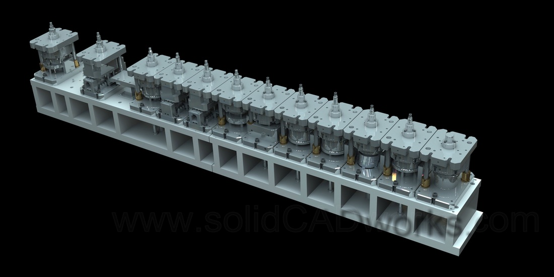
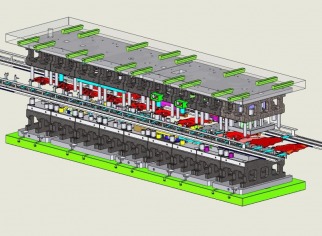
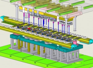
TRANSFER DIE DESIGNS
(Click here to go to PROGRESSIVE DIE DESIGNS)
Die simulations in 2004
ROTARY TOOL (2002-2003)

Design and its functionality.
Decision was taken to design a Rotary Tool considering the input part, the design target, allocated press etc.
This Rotary Tool should have to perform the following to achieve the design target. The main challenge was that it had to contain all following operations by 38mm Press Ram stroke.
1. Convert the Press Machine’s vertical Ram stroke to radial motion on horizontal plane.
2. Limit the radial motion to one direction where as Ram moves bi-direction.
3. Index the radial motion and idle at correct time for other operations.
4. Sensor the indexing with pilot sensor.
5. Insert parts to the indexing Carrier disk inside the Tool.
6. Check the thread with a sensor by emission and reflection and also thereby confirm the presence of the part.
7. Defective parts dispersal position.
8. Design an easy removable punching unit for quick Punch and Die change.
9. De-burr the piercing with a cam activated oscillating air grinder.
10. Leave some idle stations in between operations for further improvement.
11. Eject the finished part from the tool through the press bolster.
12. Compact the tool to fit and to remove easily to the press’s limited bolster area.
13. All the tool operations should be mechanical with safety precautions.
14. Add fine adjustment features.
15. Find the placement and area for press control panel and existing modified part feeder.
Considering this uncommon functionality and complexity decided to use the designing capabilities in to practice by our newly introduced Solidworks. It was interesting to work with Solidworks to build a tool with solid models that were checked their machinability and other features individually.
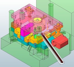
Rotary Tool Assembly in the Press
The whole tool operation could be simulated with the unique facility of Solidwork’s Collision Detection feature. It helped to cut-down the safety allowance time between operations drastically, to do simultaneous operations, determine the heights and their timings of pilots and push-rods / ejectors which should engage only at part become idle. Also it was a great help for easy and quick design change and check back and forth for optimum tool performance. With this Collision Detection feature could allocate optimum time for each operation in the limitation of 38mm Ram Stroke.
Cam activators and Air grinder
With Slidwork’s solid model, could see all the corners and edges in 3D model and it helped to compact the tool to fit to the press. Also could check that the whole tool can be inert and remove easily from the Press bolster blocked by three Ram guide Pillars.
Utilizing the tool designing concepts and standards the design was completed and with the approval of the Engineering Manager the detailed drawings were issued for the production of the tool.
The Tool was built and later with minimal fine tuning today it’s in operation with a tested speed beyond the required production speed.
This design target and production of the design could achieve as initially planned and scheduled. It’s no doubt that unless the help provided by Solidworks for this project, it will be an impossible task to complete by staying within the limitations of the allocated press and other parameters. Solidworks became the backbone of this project and without it the plans and schedules would have changed or project would have been altered.


